How about when half of it is liquid propellants? How about when it includes all of the deadweight—fuel tanks, turbopumps, and engines—associated with liquid propellant engines? How about when it makes no attempt to solve one of the major problems of solid-propellant technology: thrust vector control? Hi wonk readers! Jeffrey has kindly taken off my training wheels and let me be a guest blogger on his outstanding armscontrolwonk in my own right. I had thought I’d start my tenure here with a series of posts about Iran’s liquid propellant missile development program but I’m going to postpone that start until tomorrow. In stead, I thought I would weigh in on Iran’s solid-propellant missile. Ooops! I mean to say on their new liquid-propellant missile. Wait, that’s not exactly correct either. You know the one I mean; it’s the liquid-propellant missile with a solid-propellant motor in it. They call it the Sejil.
I’ve just come back from Croatia where the hotel’s internet was so flaky that I couldn’t do anything, so this post has been delayed by several days. I heard the news that Iran had launched a “two-stage, solid-propellant missile” with a range of 2,000 km literally as I was boarding the airplane on my way to London. I spent the entire flight wondering how I could be so wrong about the status of Iran’s solid-propellant development program. You see, there was no evidence that Iran had even experimented with thrust vector control (TVC) techniques suitable for solid propellant missiles. Graphite jet vanes, like Iran uses on its Shahab and its derivative missiles, corrode and fail very quickly in the high temperatures and corrosive environments associated with solid-propellant grains that use aluminum powder to boost their specific impulse. Fluid injection, like India used for the first stage of its SLV-3 (and the Agni I), requires considerable development both on static test stands with multiple degrees of freedom and flight tests on smaller missiles. The use of flexible nozzles also requires considerable R&D. None of which has shown up on Iranian short range solid-propellant missiles. Instead, they had seemed to be developing aerodynamic controls for these missiles instead of TVC. In particular, they have experimented with canards on some of their short range solid-fueled rockets; avoiding the entire TVC issue all together.
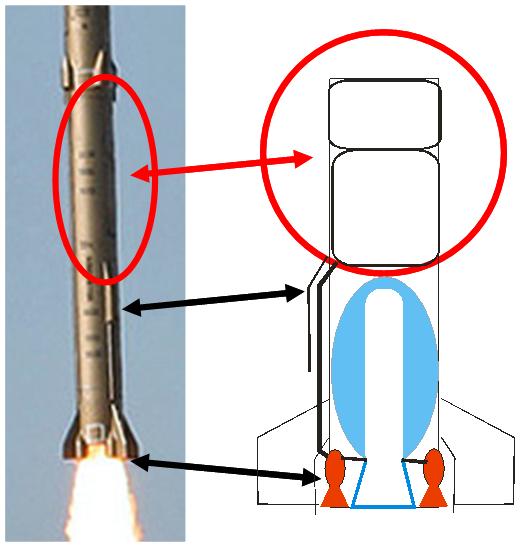
In contrast, and this was the really surprising thing, I think they used fairly large gimbaled engines to accomplish TVC for the Sejil. We know they are fairly large because the fuel and oxidizer tanks take up half of the first stage volume. The clincher that this was a largely liquid propellant missile, by the way, is the piping coming from the middle of what many supposed to be a solid propellant combustion chamber. Judging from the weld lines seen in other images of the Sejil, the missile uses over five tons of kerosene/nitric acid to power the four gimbaled engines in the first stage. (There is no indication that I can see that the second stage was anything other than an airframe with inert weight inside. Has anybody seen reports that it actually was live? This would explain the Fox report that it suffered a “failure” and only flew 180 miles.)
Using liquid propellant engines to provide TVC for the Sejil does nothing for Iran’s development of solid-propellant missiles and is far from a major advance in their technology. It could be argued, however, that the Sejil does advance the liquid propellant technologies Iran has been trying to perfect with the August launch of the Safir with its cluster of twin gimbaled engines. Of course it’s possible, since I’m still working out the numbers, that adding a solid propellant boosting motor has substantially increased the payload capacity of this missile. In any case, Iran has continued its unique missile development path. Some of their innovations have been brilliant but I cannot help thinking that this one is pretty much a dead end.
There are still problems with my interpretation, namely, what I refer to as cowlings seem to hang down farther than I would expect steering engines to hang. That argues in favor of jet vanes. On the other hand, what is that pipe coming out of the middle of what is supposed to be a solid-propellant casing? Because of this, and other details, I believe that this is the correct interpretation, but I await your comments!
Tomorrow, I’m going to start a five part series of posts about Iran’s liquid propellant missile development program. The first installment will be a speculative piece asking about what evidence exists that Iran is trying to develop higher energy propellants than SCUD-type mixtures of kerosene and nitric acid. Until then, I look forward to your comments.

If the first stage had a gap between two long propellant grains, the suspicious pipe amidships could serve to duct (solid-fuel) reaction gases to the four steering cowlings (or to a manifold that feeds them). The reaction gases could power the steering mechanisms, or be injected (at chamber pressure) into the nozzle down near the base to provide TVC without four telltale side plumes.
My only problems with this theory are that solid-fuel byproducts are very nasty and include molten aluminum, which does not lend itself to being piped around without clogging the pipes. I’m also unsure about the structural implications of perforating the case like that.
This probably doesn’t qualify as a profound technical comment, but it struck me that the smoke trail of the Sajil seemed rather anemic. Perhaps because, as your hypothesis suggests, the solid rocket was only providing part of the thrust???
I will make some short points:
The Chinese solid fuel M9/DF-11/DF-15 (Pakistani Shaheen-2) use jet vane TCV. Those are very much like the old SCUD type jet vanes, if not the same.
That box is just a retro-rocket or a solid fuel booster for trajectory change after burn out. The pipe just connects it to the missile’s autopilot.
I would say it’s a perfectly fine solid fuel missile, with some confusing Iranian style solutions.
Pedro:
Interesting point about the M9 etc. missiles using jet vanes. But are they graphite? Its my understanding that any missile that uses aluminum powder has a very hard time using jet vanes unless they are of an advanced metallurgy. Does anybody know for certain?
I’m afraid that the pipe I point to does not contain the cables connecting the guidance system to the TVC system. That is a pipe on the other side that runs the complete length of the first stage and then, after disappearing into the interstage section for a brief length, reappears on the outside of the second stage.
@Geoff Forden
Its not known if the Chinese solid fuel is HTPB, it might be somewhat different in order to minimize the aluminium problem.
Here is a picture of a Pakistani/Chinese Shaheen:
http://www.defencetalk.com/pictures/data/3045/Pak_Shaheen_defencetalk.com.jpg
The TCV system is visible and the colour of the vanes looks like that of the Shahab-3/SCUD, namely like silver/aluminium. I imagined graphite to be darker, but it might just be the skin that looks like aluminium.
That box must be connected to the missile in some way, that’s why I think that the pipe is just for the cables. It runs down to the engine section, meets with the main cable line you mentioned and is thus connected to the autopilot in the top of the missile.
Dear Mr. Forden,
i think you are definitely wrong in interpreting the fairings and the cable ducts on the sides of the first stage of the Sejil as fuel lines for a liquid-fueled vernier engine. As i wrote in my comment to Mr. Lewis’ article “Iran Claims Solid-Fueled 2 Stage Sejjil”, i think these fairings do bear a striking resemblance to the retro-rockets of russian missiles like the R-14/SS-5/Skean. The “piping” is just a cable duct for the associated wiring. If these ducts would contain fuel lines, wouldn’t you expect the lines for fuel and oxidiser to have different lengths (take a close look at the backside of the missile – both fairings end at the same height!)?
Furthermore, there are no additional flames next to the main-engine exhaust plume visible – compare this to known missiles with vernier-engines like the MR-UR-100/SS-17/Spanker or the R-29RM/SSN-23/Skiff.
And obviously, there is much less of a problem with graphite jet vanes and aluminized composites than we in the west do expect (although i still haven’t figured out how exactly this can work – there must be some kind of trick, maybe a special coating or additive). There are lots of examples for this configuration obviously working pretty well: Tochka/SS-21/Scarab, Iskander/SS-26/Stone, Pionier/SS-20/Saber, Topol/SS-25/Sickle, DF-11/M-11/Ghaznavi/CSS-7, DF-15/CSS-6, M-9/Shaheen-1 and M-18/Shaheen-2, just to name some of them. The only other material that i ever heard of being used in jet vanes was Molybdenum (on the successless german A3-experimental-missile – after that, the material of choice for A5 and A4 was…yup, graphite!), although i guess that modern hi-tech-composite-ceramics like SiC could perhaps also work.
To Pedro:
I completely agree with you!
(except if your intention was to suggest that the jet vanes on chinese solid-boosters were made of aluminum…a material with FAR too insufficient thermal properties; By the way, at certain angles graphite can look metallic shiny.)
yes, and the possible vane that flew off of the earlier Iranian test also looked silvery.
I think we may be locking ourselves into unnecessary assumptions. Assumptions need to be made, but let’s not pretend that they are necessarily correct.
Dear Jochen: (if I might address you like that, since I really do feel quite friendly toward you and respect your knowledge of missiles)
Yes, we definitely disagree about that external pipe. The fuel pipe could quite easily pass through the oxidizer tank as it does on the SCUD. And I think you need to think some more about having high pressure gases leaving from the middle of a solid-propellant motor casing. It would cause all sorts of problems!
I would also say that placing 4 gimballed venier engines into a 1.25 diameter missile body beside a large solid fuel sustainer’s rocket would be a pretty huge engineering accomplishment. It was also one of my first thoughts, but after realizing that it’s obviously a solid-fuel rocket I dismissed it for being far to complex.
@Jochen Schischka
Surly not aluminium but how about some metaloxide-ceramic combinations, today this would be more likely than graphit, not to talk about molybdenum.
An aluminiumoxide-ceramic for example might have that bright grey colour of those jet vanes.
Dear Geoff: (I guess we’re all friends here ar ArmsControlWonk.com, right?)
I’m not sure you did understand me right. I never suggested to bleed off hot high-pressure-gasses from the main chamber through these ducts (that was JR’s idea – and i think we’d see them glow at least bright red in the photo accompaning this article if that was the case). My suggestion was that there are two small solid-propellant-rockets bolted to the outside of the first-stage-missile-motor (connected to the tail section of the missile by small external cable ducts) which are ignited during staging to decelerate the burnt-out (but possibly not completely outgassed -> no thrust-termination!) lower stage with the intention of avoiding a potentially unpleasant collision after separation of both stages and before the upper stage ignites.
And if you’re obliged to have both an external fuel and oxidiser line anyway (unless you’d want them to run right through the solid-rocket-combustion-chamber…a really, really bad idea if you ask me!), then why bother with putting the first half of the fuel/oxidiser line inside of the oxidiser/fuel tank? Please consider the V-75/SA-2/Guideline, V-200/SA-5/Gammon or the iraqi Al-Samoud-missiles as examples for external fuel lines.
By the way, i’m looking forward to your announced series on Iran’s liquid-fueled missiles – i think that will be highly addictive reading…
Quite right! I’m afraid I did confuse your agreeing with Pedro with something JR said. Sorry about that!
I suppose I need to show some more pictures to help explain my case better. Consider this one, which is a close-up of the portion I call the liquid-propellant section:
This clearly (at least to me) shows the upper half of the first stage is composed of two welded sections, the upper one being roughly half the size of the lower section. That is consistent with kerosene/IRFNA.
Ignorant question: Is it sure it has a solid motor?
If four liquid fuel engines are used for TVC, why do they need to be gimbaled?
the author is indeed an armchair analyst which makes a bold judgment based on a pipe sticking out in the end. This could be many other possibilities. Seems that he didn’t watch the movie and see the smokey trail of the missile, a positive indicator of solid fuel. Also, he missed the faster acceleration of the missile during take off something not seen in older shahabs.
Distiller-
You can tell that it is indeed a missile with a major solid propellant motor because of the long lasting column of “smoke” that is left behind. This is caused by the particulate component of its exhaust plume, almost certainly containing a large component of aluminum particles. If you look at films of the Kavoshgar-1 launch in February, you notice that the smoke column disappeared almost immediately behind the missile. The US space shuttle, which has both liquid- and solid-propellant engines, also leaves a persistent smoke column because of its solid-propellant strap-on boosters.
Medhi-
You certainly could, in principle, throttle the four liquid propellant motors differently to control pitch and yaw. But you would not be able to control roll like that. On a deeper engineering level, SCUD-type engines have their thrust controlled by adjusting a pressure gauge-type regulator that might be very hard to replace with a more dynamic control. Furthermore, Iran is known to be developing gimbaled engines for its Safir missile. (See “my comments on the Safir”: http://www.armscontrolwonk.com/2004/forden-on-safir-e-omid .) And it seems to me that it is simpler to continue on down a development path once it is started than to try two competing paths at once.
For those of us who have seen many Shahab’s missile launches, certain supporting equipment for liquid fuel loading are easy to recognize. Also pre-launch video of liquid fuel propelled Shahabs have clear signs pointing to the recent fuel loads. Those equipment, preperations, and other signs were certainly not present in the complete video shown in Iran of the “Sajjil’s” launch. Unless IRGC has a totally different method of fuel loading which is very unlikely.
Or that Iran wants to hide the fact that it uses liquid propellant steering engines.
Actually some of the earlier reports appearing in Iranain press did say combination of liquid + solid fuel was used.
“ The new deterrent missile, called Sejjil, burns a combination of solid and liquid fuel, sources at the Iranian Defense Ministry told Press TV.” Source: http://www.presstv.ir/detail.aspx?id=75135§ionid=351020101
Most other reports were pointing to solid-solid engines/stages.
Still most evidences so far point at no presence of any liquid fuel.
To Geoff:
I’m still not convinced of your theory – the quality of the available photos simply is too low to make definitive statements on that subject (i’m wondering how you could identify a row of bolts on that photo?), although i’d suggest to also have a good look at the longitudinal weld joints. I can’t tell for certain, but they seem to indicate a different configuration (almost 1:1, not 1:2) than you presented. By the way, if this is a Scud-C-like common-bulkhead-configuration as you obviously imply, then 1.) the lower end-dome of the fuel tank would protrude into the oxidiser tank, producing a slightly different volume-ratio of both tanks (something like 1:2.2 or 2.3 if this is IRFNA/RP-1…) and 2.) i’d expect a characteristic double-weld joint between both tanks – but i guess we have to wait for higher-resolution photos to ultimately solve that question.
There are also other things to consider. For example: where exactly does the solid-rocket booster end? Above or below the upper end of the “fuel lines”? How is the liquid propellant delivered into the chambers? In which part of the missile would a hypothetical turbopump and/or pressure-gas-system be installed? Where are the associated access-panels and fill-/drain-valves? And especially:
Why are no additional flames next to the solid-rocket exhaust plume visible (even UDMH should produce observable flames)?
On the other hand, i completely agree with your answers to Distiller and Mehdi. By the form and colour of the rocket flame we even can identify the propellant as some sort of composite – either some type of HTPB or PBAN. And steering by throttling rocket engines was obviously one of the reasons why the russian N1-rocket never worked satisfyingly.
To kpars:
Not seeing something in the official footage doesn’t automatically mean that it isn’t there. On the other hand, Shahab/Scud/NoDong-line uses storable liquid propellants (TM-185/AK-27I/TG-02) – there is no need for fuel handling equipment in the vicinity of the launch site.
Addition to my last comment:
The Scud/NoDong-line missiles are checked, mated with the warhead and pre-fueled at a special operations base. After that, all other equipment necessary for launching should be installed on the TEL/MEL. By this, you have the instantaneous launch-capability and independence of a solid-propellant booster combined with the option to store your missiles unfueled for a long, long time (solid propellants age and have to renewed at around 10 years – although the russian Topol/SS-25/Sickle obiously still works after 20 years!).
I advise the auther to visit iranmilitaryforum.com in the thread http://www.iranmilitaryforum.com/forum/index.php/topic,16356.100.html a detailed yet sarcastic rebuttal is available for him.
From a purely editorial point of view, I might have said “a sarcastic yet detailed rebuttal…” That way, it makes the sarcastic portion seem more important. Your order emphasizes the detailed. Just something to keep in mind.
Geoff Forden: here is some sarcasm for you to laugh about.
definiton of armchair expert: A person who makes bold claims from his armchair based on a couple of pictures. I would make sense though if you put in a probability factor in your claims and use words like “most likely”, “probably”, etc. in your article.
Amazing that a bunch of people from a Canada-based forum dedicated to the wonderfullness of Iran’s military hardware should arrive on an off-the-beaten-track blog to tell everyone how wonderfull Iran’s military hardware is. Such is national pride from a distance.
To Geoff Forden:(About the last picture you put)
I want you to think about these photos:
http://www.farsnews.net/plarg.php?nn=M385333.jpg
http://www.farsnews.net/plarg.php?nn=M385305.jpg
http://www.farsnews.net/plarg.php?nn=M385336.jpg
There are more lines on other parts of the missile.I wanted to know how it can be explained?
Also,if the pipes are used to deliver fuel and oxidizer why aren’t they covered with anything?wouldn’t it make any problems?
So I agree with Jochen Schischka .
I have an explanation for those box-like things.Consider one of them doesn’t exist,then the missile will be derived to the opposite direction.So any change in those boxes can be used instead of TVC.Can’t it be used as a mechanism like TVC.
cerning:
More amazing is an allegedly mit class anal-yst make such strong conclusions based on minimal information. No quality engineer or a university-class character would write like that.
Mohsen and Ali:
Most likely she is trying to secure her income after bush admin is gone.
She knows sensitivty around Iran’s achievements and seems very desperate to make fox style noise. In fact, she cited fox news in his analysis.
Omid—
I must admit that I have been confused by some of these pictures. The question I’ve asked myself is “is that the same side of the missile slightly rotated with the cable race track rotated out of view, or is it the opposite side of the missile with a similar short pipe?” Unfortunately, the cable race track (if that’s what it is) in this photo is blurred and somewhat hard to recognize:
http://www.farsnews.net/plarg.php?nn=M385333.jpg
but lets assume that it is the same cable race track as in this picture:
http://www.farsnews.net/plarg.php?nn=M385305.jpg
only the missile is rotated so it appears on the opposite side of the missile. In that case, there are two similar short pipes running up to the same height of the missile (about halfway up the first stage). Now, I am more convinced that there are two such pipes. But what does that imply? Both could still contain both oxidizer and fuel lines only delivered to opposite sides of the solid propellant motor; each to two separate pairs of steering engines. And, since neither is cryogenic, there doesn’t appear to me to be any problem to me to running them on the outside. As others have mentioned, Iraq’s Al Samoud II also ran fuel lines outside the airframe.
One thing about writing a blog post is that you have to make it short enough to be read by people who are not inclined to read long expositions. It is very different from writing an article in a peer-refereed journal. So writing technical posts is something of an experiment but I hope that by responding to readers’ comments—and the back and forth discussion that entails—can make up for that. There is, of course, a back history to my analysis that I haven’t had a chance to present. For instance, as I mentioned in the post, Iran is known to have experimented canards to aerodynamically steer its shorter range solid-propellant missiles and there has never been an indication that they experimented with using jet vanes to guide these same missiles; something you would expect before risking the failure of a major missile like the Sejil. And that is as close as I am going to get to responding to comments that are obviously intended only be to insulting (and I do not mean yours, Omid) and not to contribute to the community arriving at an increased understanding.
Looking at the MEHR photos 404965 and 404968, it’s clear that there are two of them and they’re aligned with the #1 and #3 fins. Since the 1-3 axis is traditionally (at least with the V-2 and Scud) the pitch plane, is it possible that these are just structural, and intended to reinforce the first-stage motor case during pitch maneuvers?
If they’re reusing guidance calculations they’ve done for other similar-diameter systems, this (much longer) missile would be subjected to pretty aggressive pitch commands.
Geoff, I’ve definitely abandoned my idea that they could “tap” the motor amidships – that’s just asking for trouble.
@Geoff Forden
The reason they haven’t (at least in public) used TVC for guiding the Fateh is simply because its trajectory is not exo-atmospheric.
However we haven’t seen missiles like the Ashura in public, it might was a predecessor of the Sejil using TVC with solid fuel. There are surly unreported things going on in the background, otherwise there wouldn’t be such a technology as we see in since some time.
Since I’m sticking to the jet vane version it seems like the Iranian engineers have designed a to some degree variable jet vane system, since those “boxes” could be attached to missile bodies with larger diameter. Their uniqueness also points to a new development in the TVC area connected with the problems of SCUD type jet vanes and solid fuel. A somewhat heavy but maybe effective tungsten-carbide jet vane could be the breakthrough technology if Graphite is that problematic.
To Omid:
You mean as some sort of aero-brake?
Consider:
1.) inherently higher aero-drag-losses and thus, lower achievable range;
2.) will not work when ram pressure is too low, e.g. at slow speeds or high altitude;
3.) excessive forces at or around q-max; might be problematic around Mach 1;
4.) no flap-mechanisms visible (well, at least not on the pictures available to me);
5.) Why the position that high up? Why not on the tail section?
To JR:
The positioning of the missile on the launching table in relation to the MEL lets me come to the conclusion that the two “sideboxes” are aligned with the II-IV-plane of the missile, and that there is only a single cable duct at the I-side of the Sejil (in contrast to the two ducts at the II- and the IV-side of the Scud), so this would be the yaw-axis. But since i haven’t found any numbering on the fins yet, i could of course be wrong.
I consider your structural-reinforcements-idea as somewhat improbable because of several reasons:
1.) The missile is not considerably longer than Shahab-3 or Ghadr-1/Kavoshgar-1 (photo-measurement) and in fact shorter by several meters than Safir – so there’s no need for a more aggressive pitch-program (in fact, i wouldn’t be surprised if most of the pitch-over had the form of a gravity-turn anyway).
2.) On a solid-booster, the fuselage has to be built stronger than the tanks of a liquid-booster to last the chamber-pressure, which additionally helps stiffening the cylindrical body of the missile during flight.
3.) Why don’t the “reinforcements” cover the whole length of the first stage? Why this complicated configuration with a box-shaped cowling on top and a thinner lower part?
That said, if my retrorocket-hypothesis is correct, then i don’t understand why the iranian engineers (or whoever designed this) didn’t do away with the additional cable ducts by simply mounting the rocket-packs lower…
To Geoff:
I think you mean the Al-Samoud, not the Al-Samoud II (which had in fact a Scud-like internal fuel-line).
Al-Samoud is in my opinion a very good example for external propellant-lines: on the one side of the missile runs the short fuel-line (overbridging some sort of pressure-gas container if i remember that correctly), and on the other side the MUCH LONGER oxidiser-line is reaching all the way up to the oxidiser-tank…
To Geoff:
Then if the boxes cover the liquid-fueled ones,why does the second stage contain these boxes but doesn’t have such pipes?
And if the liquid-fueled ones are to navigate the missile why are they so big?(I think they are not for boosting the missile because the solid-fueled one can provide higher thrust)
Jochen,
I was assuming a Safir-like orientation on the MEL, given the similar diameter and handling equipment, which puts the #2 fin on the (U.S.) passenger’s side of the MEL pointing up. That is, if the MEL parks facing north and elevates the missile, the #2 fin will point southeast. The sideboxes — it’s as good a name as any — seem to be on the other two fins from what I can see, but you’re right that we can’t know the fin numbering for certain.
In this pic (http://www.farsnews.net/plarg.php?nn=M385295.jpg) the flag is blowing right-to-left, the strongback of the MEL is folding down towards the camera, and the sidebox appears to be on the right ventral surface of the missile. In this picture (http://www.farsnews.net/plarg.php?nn=M385305.jpg), another flag (there is no shortage of flags at the site – look at http://www.farsnews.net/plarg.php?nn=M385307.jpg) is blowing left-to-right, and the strongback is folding down away from the camera. The sidebox is visible on the left dorsal surface of the missile.
The writing on the airframe negates the possibility that these two sideboxes are the same — in one picture there is writing up the length of the airframe to the left of the sidebox; in the other pic the missile is clearly unmarked.
I like Pedro’s (far simpler) solution that they are retros or flight-test hardware of some sort, but unless someone publishes a labeled schematic, or Ahmedinejad does another factory tour, we’re probably going to just keep guessing.
Meanwhile there are photos around which show that the “fuel pipe” of the venier engines theory is very slim, much slimmer than the two main cable ducts, which hints to a cable-only duct.
Additionally the missile “sits” on those boxes when erected, the whole weight carried by them. Therefore it seems rather unlikely imo that those constructions house venier engines and the static construction able to carry the whole weight. But what’s more is that the low quality photos apparently also seem to show jet vanes.
I’m sure the material will show up soon.
Just wondering about the technical issues related to 4 liquid propelled TVC engines: from the drawing suggested by Geoffrey, and after close examination of the pictures from the launch, it is clear that almost the entire vernier engines is exposed to the flame and exhaust of the solid fuel rocket motor. I have never encountered an engine which could withstand these conditions. I am not talking ONLY about the extreme temperatures, but the erosion of the Alumina in the exhust. It is my strong belief that the Sejil / Ashura is using jet vanes and NOT small , liquid fueled vernier engines.
Tal—those are very good points and I have to admit my convection is being shaken. So what do you think those pipes running up the side are?
Geoff,
those pipes running up the side are still a bit mystery. The upper section of the pipe COULD be a retro rocket (although from the pictures – and especially the animation of the Safir the Iranian retro rockets has different shape.
BTW, from the shape of the flame and exhaust I thing that your estimate regarding the dimensions of the nozzle is not correct. I think the diameter of the motor casing is slightly less than the 125 cm exterior diameter of the missile, and, that the nozzle is much wider than your drawing.
Judging by the way Iran is parading its missiles, I believe that the Sejil/Ashura WILL BE ON DISPLAY at the next big parade and we than will be able to analyze it better.
If my conviction is shaken, I don’t think I’ve abandoned it quite yet. There are, after all, many problems with the jet vane theory, besides the developmental history ones I’ve pointed to above. After all, if we imagine that the little boxes cover the front end of jet vane servos, then they too are subjected to the environment that you mention, in particular the corrosive nature of the exhaust. Perhaps they could be beefed up more than the nozzles of liquid engines. But then, again, I’m not so convinced that the solid propellant motor’s (SPM) nozzle fills as much of the end of the missile as you are. For instance, isn’t it possible that the exhaust from vernier engines creates shockwaves where it hits the main rocket exhaust and effectively mixes with the opaque exhaust from the SPM’s exhaust? That might cause us to think that the SPM’s nozzle appears bigger than it is. Finally, I cannot help thinking that the side pipes are very, very important for understanding this missile. That has been my thinking from the very beginning. If they are retro-rockets associated with staging, why place them so near to where the center of mass of an empty solid propellant first stage would be? I haven’t modeled it yet (too busy writing these posts!) but it seems likely that a first stage that was totally solid propellant, it would stage well inside the dense part of the atmosphere. If so, I would put the retrorockets as far toward the bottom of the missile as possible. Otherwise, it seems to me, you run into stability issues as you separate and might be worse than no retrorockets at all. If, on the other hand, the Sejil stages well above the dense part of the atmosphere, then I would place retrorockets near the top end of the first stage. That just seems simpler to me. I cannot imagine a reason for putting them in the middle. So, as you, I look forward to seeing pictures of the tail end of the Sejil.
To JR:
And i assumed a Scud-like orientation (the Safir should be using the same pattern – although one has to bear in mind that the launching stool of all these missiles incorporates a 360°-turntable), where the fin no. I on the erected missile points northwest if the MEL is facing to the north (you can check this out on pictures of Scud-operations or museum display-pieces). Otherwise i agree with you.
The way the author goofed in his new article: http://www.armscontrolwonk.com/2098/whats-with-the-goop
In which he made an obvious mistake identifying Pakistani Ghauri as Iranian Shahab 3, one wonders how much credit should be given to such “open source”, aka armchair, analysis.
To Geoff:
Considering vernier-engines on the Sejil, i would rather expect a central, conically widening exhaust plume (characteristic of solid-fuel rockets) surrounded by four short flames that do mix somewhat with the central flame, creating a plume widened near the missile, then contracting slightly (when the short liquid-fuel plumes end), then widening again in straight, conical fashion while evolving into a white smoke trail.
What we see on the actual missile is in my opinion a straight conically widening solid-fuel exhaust plume without additional liquid-fuel flames – so i assume that there are no additional liquid-engines.
On the issue of the “sidepipes” (i like this name, i think i’ll use that from now on):
Although i was the first to suggest the retrorocket-hypothesis based on optical resemblance, i agree with you. A somewhat strange place for rocket-packs that furthermore shouldn’t be even necessary for staging in the lower atmosphere.
But maybe you stumbled yourself over the right answer: if the thickened box-like upper parts of the sidepipes are really retrorockets (and if staging happens at high altitude), then it could perhaps be reasonable to put them near the center of mass of the burnt-out stage: separation would happen at a specific slant angle off of the vertical on a surface-to surface-missile, right? If the retrorockets exert force on the empty stage away from the center of mass under this conditions, then, as i understand, due to the pull of the gravitational force the stage would start to pitch up (rocket force application point in front of center of mass) or down (behind c.o.m.), although i must say that i’m not certain if this would really matter on a burnt-out, separated stage.
Can somebody with a more thorough understanding of mechanics than i please crosscheck this issue and tell me if i’m right (as i hope) or wrong (as i fear)?