Right on time, ISIS has released the Safeguards report for Iran — Implementation of the NPT Safeguards Agreement and relevant provisions of Security Council resolutions 1737 (2006), 1747 (2007) and 1803 (2008) in the Islamic Republic of Iran GOV/2008/15 (May 26, 2008).
And the big news, at least from the wonky angle, is a new centrifuge design, the IR-3:
3. On 10 April 2008, Iran informed the Agency about the planned installation of a new generation sub-critical centrifuge (IR-3) at the Pilot Fuel Enrichment Plant (PFEP). On 19 April 2008, the Agency confirmed that two IR-3 centrifuges had been installed at PFEP. In February 2008, Agency inspectors noted that Iran had also brought 20 IR-1 centrifuges into PFEP, which were run in a 20-machine cascade for a short time, after which they were removed.
Why is Iran building an IR-3 before mass producing the IR-2? As I understand it, the IR-2 is an interim design until Iran can design better scoops — tubes that withdraw the enriched uranium — that will allow the IR-3 take advantage of the faster speed of a carbon fiber rotor.
What The Hell Are Scoops?
Scoops are little bent tubes that withdraw the enriched uranium from the top of the centrifuge.
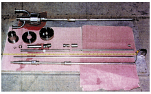
Figure 22.2.10. Centrifuge columns and
a scoop found in Iraq. A column with
feed, product, and waste connections is
shown at the top of the photograph, and
a scoop is attached to the column at the
bottom of the picture. The scoop extends
from the right end of the column and
touches the tape measure.
DOE published the best description and picture — well the only picture — of scoops I could find in Annex 3 of the Handbook for Notification of Exports to Iraq.
Scoops are small tubes designed to operate in a fixed position inside a spinning gas centrifuge rotor to extract UF6 gas and transfer it to the center post where it is removed from the centrifuge machine. A centrifuge scoop is similar in appearance to the Pitot tubes used on aircraft to measure airspeed. Figure 22.1.1 shows a cutaway view of a centrifuge machine with scoops located at the top and bottom inside the rotor. Each scoop is permanently mounted to the center column with ends very close to the wall of the rotor. Figure 22.2.10 shows a typical centrifuge column with a scoop attached to the end of the column.
The length of the scoops is slightly shorter than the radius of the centrifuge rotor. Scoop tube diameters can be up to 12 mm, although scoops with larger diameters have been produced. One end of the scoop is bent to face the gas flow within the rotor tube and the other end is attached to the fixed center column of the centrifuge. Each scoop is manufactured from UF6-resistant materials. Typical materials of construction for gas centrifuge scoops include copper, aluminum, and stainless steel.
These are pretty tough to manufacture so that they don’t disrupt the internal gas flow. Pakistan imported a bunch of preforms, which produced a very nice explanation of scoops by ISIS.
IR-3 and Scoops
I first heard that Iran was working on an IR-3 after Ahmadinejad’s office released pictures of him strolling through Natanz. Iran, it was quite obvious, had assembled a cascade of IR-2 centrifuges.
Experts thought Iran wasn’t ready to install cascades, based on reports that Iran was having trouble developing scoops to withdraw the product. Bill Broad even quoted one anonymous European expert talking about difficulties with the IR-2, although he didn’t specify the nature of the trouble:
A European centrifuge expert who closely follows the Iranian program, including the evaluations of international inspectors, said difficult work remained on the IR-2. “They obviously have months, if not a year, of test work to do before they can consider proceeding with mass production,” the expert said, who spoke on the condition of anonymity because of the issue’s sensitivity.
That was probably a reference to the scoops, which were noticeably absent on the table of components.
So, one quite plausible suggestion was that Iran was installing a less than optimal IR-2 design in cascades, while working to manufacture a better scoop for a third design (the IR-3) that would make fuller use of the tensile strength of carbon fiber.
After Iran reported it to the IAEA, word got around.
IR2 and IR3 Estimates
Working from these assumptions, our friend Scott Kemp sends along some calculations on the IR-2 and IR-3.
| Design | (is like) | Speed (m/s) | Super- critical? | SWU (kg/a) | Current number, location and status |
|---|---|---|---|---|---|
| IR-1 | P-1 | 330 | supercritical | 2.5 | > 3000 machines installed in cascades |
| IR-2 | short P-2 | 450 | subcritical | 2.2 | ~10 machines in one cascade, plus some stand- alone machines |
| IR-3 | short P-2 | 600 | subcritical | 4.0 | ~2 prototype stand-alone machines |
Note. IR-1 is SWU estimate is based on observed efficiency of 42%; IR-2 and IR-3 based on an estimated efficiency of 60%.
Scott notes, based on the report, that Iran “is getting better results with its IR-1 (P1) cascades. The early cascades were suffering from instabilities, requiring low feed rates, high mixing losses, and low effective SWU values.”
Presumably Iran’s choice of whether to mass produce the IR-2 or IR-3 will reflect their success in developing better scoops.

Funny how the media’s characterization of the recent IAEA report is so inconsistent with the report itself
Jeffrey,
I read a message 5 days ago that You are on holidays…The IR2 story makes great reading, even when one has to work.
Happy holidays!
Great post! Once again ACW is THE place to come for technical information about the latest developments in proliferation. I especially like your table. If I could suggest one addition to it for this story in particular: add a column giving the Mach number of the scoop as it passes through the UF6 gas. Since the speed of sound in UF6 is about 97 m/s, the drag forces on the scoop (and the heating of the scoop) will change dramatically for the different speeds. This shows why design of the scoop is so important (and difficult!). For the IR-1 (with a rotor speed of 330 m/s) the scoop is at Mach 3.4; for the IR-2 (rotor speed = 450 m/s) scoop speed = Mach 4.6, and for the IR-3 (with a rotor speed of 600 m/s) scoop speed = Mach 6.2.
http://www.president.ir/piri/media/main/28863.jpg
I think it is IR-3.
but do you think IR-2 is weaker in enriching uranium and iran still wants to produce it,and why cooling coils are wrapped only around a small part of it?
Omid:
For some reason, I couldn’t follow your link to the picture you refer to but if it’s the one I think it is, they are heating coils and not cooling coils and they are still in the process of being assembled. The heating coils are pulled up during assembly and fastened to the top of the outer casing with a screw and loop device. These heating coils help establish the thermal gradient along the axial direction of the centrifuges as well as make sure that the UF6 doesn’t solidify, which it would if it cooled down. Since it seems that the only difference between the IR-2 and IR-3 is the design of the scoop (thanks again for bringing this out Jeffrey!) it is probably impossible to tell the difference between the two from just looking at the outside. (Of course, they might sound differently if you were there since they are spinning at different speeds.) However, since all the images of centrifuges appear to come from the Fuel Enrichment Plant and not from the Pilot Plant, I would guess it was an IR-2. (Again, since I couldn’t follow your link, it might be in the Pilot Plant but I dont recall any from there.)
One other thought: if IR-3 and IR-2 do really differ only in the scoop design, it might be possible (and make economic sense) for Iran to install a large number of IR-2s and then retro-fit them to IR-3s once the scoop development is finished. That might only involve the replacement of the center post or possibly only the scoop itself. This might explain why Iran is continuing development of both the IR-2 and the IR-3 in parallel. Could they do the same thing to the IR-1 but replace the rotor as well as the scoop? I think not and here is why: If the IR-1 is really based on the Pakistani design, then the motor is probably incapable of speeds much in excess of 330 m/s. Replacing the motor would be a messy and time consuming process since it is “potted” into the outer casing. This epoxy must be dissolved or machined out and in either case would risk contaminating the centrifuge. While it is possible to do this, and certainly has been done on research centrifuges, the chances of mistakes on an industrial scale seem prohibitive. At the same time, the outer casing, while still involving precision engineering and therefore represents a significant investment, is perhaps the least demanding manufacturing step.
Here’s Omid’s picture – there was an extra “/” in there that broke the original link.
Geoffrey…
Omid’s link contains a typo.
This is the image
Geoffrey, the coils are most probably still cooling coils, as for the P-1. The heating comes from inside. Heating a casing would not be effective anyway for setting up a gradient from top to bottom.
As for the picture, since GOV/2008/4 speaks of TWO subcritical designs, it is likely the picture of OMID is showing an IR-3 with whatever modifications.
I agree with Geoffrey that the coils will be pulled up during assembly.
Richard, you certainly could be right but how do you heat something spinning at 360,000 rpm unless it is thru the outer wall (by either conduction or radiative heating)? I still believe they are heating coils but I’d be interested in being proved wrong and if you can send me some blueprint or design that shows how they do it I’d very much like to see it.
I’ve only skimmed the report so far, but this paragraph really jumped out at me:
The previous report (GOV/2008/4 para 37) labeled the info, “…certain documentation which the Agency had been given by other Member States, purportedly originating from Iran…”
This quite significant change reminds me of Andy Grotto’s post about China providing intel to the IAEA. The implication, obviously, is that China has provided corroborating information.
It seems the Agency appears to be pretty confident in the legitimacy of the info for the “alleged studies” and perhaps that’s what explains the definite change in tone of this report.
It’s Phase diagram of UF6:
according to the phase diagram in 30˚c UF6 is solid and cannot be used in centrifuge,so maybe they are heating coils.
Geoffrey, there is as far as I know only one heat source, cf.
Cunzhen, Zhang and A.T. Conlisk, “Separation in a gas centrifuge at high feed flow rate,” J. Fluid Mech. 1989, vol. 208, pp. 355-373, the motor, fixed to the rotor.
As for the RPMs …lo and behold…..even the 600 m/s only translate to 76,400 rpm !
Sorry Richard, but I don’t see any practical design information in the paper you reference. While interesting, it is a comparison between a linear temperature distribution and a nonlinear (quadratic? which is the other temperature distribution that can be easily solved with the pancake approximation) temperature distribution, both along the axial wall. No mention about the heating coming from the motor which would hardly create a linear temperature distribution along the axial wall. And it would be highly nonlinear in its control. If the motor was the source of the heat, then changing the motor speed would change the temperature distribution; a mixing of effects you just don’t want to do if you want to control the centrifuge. (And you are quite right about the RPMs, I accidentally left in the 2pi for radians; thanks! I assume the remaining difference is our choice in radius.)
I have been following gas centrifuge related scientific issues for quite a while now and would be willing to share this information with others. My coolection consists of patents, technical reports, journal articles and conference papers from countries around the world. For an analysis of scoop design issues take a look at this article in the journal Meccanica, 1980, Vol. 15, p39-46.
I’m willing to share information that is contained in my nuclear bibliographies that are posted on the FAS website. Feel free to email me with comments or questions. All my material is open source and can be shared with anyone who is interested.
Sorry, Geoffrey, yes the paper did not contain the actual design, only the theory. The design is here:
The centrifuge’s electric motor produces heat at the base of the machine, causing a temperature profile along the length of the centrifuge, assisting the separation process.
As for your counter argument. I believe motor speed is never changed. It is running in optimum mode and stays there (I am not an expert though). Fine tuning can be done only by cooling loops.
Omid: The UF6 is heated in an autoclave to about 60C, otherwise it would not enter the piping to begin with. Also note that centrifuges work in high vacuum.
Here is a better image of the device:
The image from my previous post was a direct link to the VERY s.l.o.w Iranian site.
Feel free to delete that image from that post.
In Zippe’s last unclassified report, which showed the designs for some of his early centrifuges, he indicates that the coils along the outer casing are responsible for the temperature gradient? Interestingly, Zippe shows two coils in close proximity to each other were used to produce this gradient: the one running from the bottom to the top was a heating coil while the other—which ran from top to bottom—was a cooling coil. Since they were in such close contact, the water inside each tube clearly changed temperature as they progressed up and down the side of the centrifuge. Just as obviously, it is a single coil on the outside of the Iranian centrifuges. But gravity and the natural spring tension of the coil has arranged it so that the spacing between the loops is greater at the top than at the bottom. Since it takes hours, if not longer, for UF6 to make it through the cascade, these must be heating coils. The temperature gradient would be caused by the spacing between the loops and transmits itself to the rotor by either radiation or, perhaps partially, by convection. By the way, if the motor was responsible for the temperature gradient in URENCO’s later centrifuges, something I still have trouble believing, then it too would transfer its heat via either radiation or convection since the motor is attached to outer casing (and, in fact, potted into the outer casing with epoxy).
I take back that last comment about how the heat from the motor would have to use either convection or radiation to heat the rotor. It is possible for eddy currents induced in the bottom plate by the motor to be used to efficiently heat the rotor’s bottom plate. However, I still believe that the presence of the coil on the outside of the casing implies that the designs (both the P-1 and IR-versions) are still primitive enough that they use these coils for heating and to create the temperature gradient. I’m glad to have had this “conversation” about the coils since it has forced me to focus on some of these details.
16. At follow up meetings in Tehran on 28–30 April and 13–14 May 2008, the Agency presented, for review by Iran, information related to the alleged studies on the green salt project, high explosives testing and the missile re-entry vehicle project (See Annex, Section A)…..The Agency received much of this information only in electronic form and was not authorised to provide copies to Iran.
POLITICS: Iran Nuke Laptop Data Came from Terror Group
By Gareth Porter
WASHINGTON, Feb 29 (IPS) – The George W. Bush administration has long pushed the “laptop documents” — 1,000 pages of technical documents supposedly from a stolen Iranian laptop — as hard evidence of Iranian intentions to build a nuclear weapon. Now charges based on those documents pose the only remaining obstacles to the International Atomic Energy Agency (IAEA) declaring that Iran has resolved all unanswered questions about its nuclear programme.
But those documents have long been regarded with great suspicion by U.S. and foreign analysts. German officials have identified the source of the laptop documents in November 2004 as the Mujahideen e Khalq (MEK), which along with its political arm, the National Council of Resistance in Iran (NCRI), is listed by the U.S. State Department as a terrorist organisation.
There are some indications, moreover, that the MEK obtained the documents not from an Iranian source but from Israel’s Mossad.
In its latest report on Iran, circulated Feb. 22, the IAEA, under strong pressure from the Bush administration, included descriptions of plans for a facility to produce “green salt,” technical specifications for high explosives testing and the schematic layout of a missile reentry vehicle that appears capable of holding a nuclear weapon. Iran has been asked to provide full explanations for these alleged activities.
Tehran has denounced the documents on which the charges are based as fabrications provided by the MEK, and has demanded copies of the documents to analyse, but the United States had refused to do so [provide copies].
The Iranian assertion is supported by statements by German officials. A few days after then Secretary of State Colin Powell announced the laptop documents, Karsten Voight, the coordinator for German-American relations in the German Foreign Ministry, was reported by the Wall Street Journal Nov. 22, 2004 as saying that the information had been provided by “an Iranian dissident group”.
Full piece Here.
Geoffrey, I was going to write just that. The rotor might get heated via the bottom cap which is entirely connected to the eddy current driven rotor of the motor (especially for P-2 variants, as can be seen on one of the pictures posted here).One could also argue that the plastic hoses seen in the pictures at the bottom of the centrifuges for the outer coils would make more sense for (cool) water flow than for hot water (where usually not plastic would be used for piping). Also to me a gradient of the temperature is not straightforward to achieve if you have kind of homogeneous windings all over the tube.
Anyway I am now wondering what the difference of IR-2 and IR-3 really is. Scoop is one thing, length of rotor another and ISIS thinks of improved bearing:
http://www.isis-online.org/publications/iran/ISIS_Iran_IAEA_Report_29May2008.pdf
My wild guess is on the bearing.
A very unambiguous statement by Putin:
I should say that formally Iran hasn’t violated any rules. It even has the right to carry out enrichment. It only takes a quick glance at the relevant documents to confirm this. There were some claims that Iran hadn’t revealed all its programmes to the IAEA. This is what we need to clear up. But to a large extent Iran has revealed its nuclear programmes. I repeat there is no official basis for legal claims against Iran.
source
Here’s an abstract from a paper given at the 2004 International Nuclear Science and Technology conference held in Iran that may help shed light on their activities:
Feasibility Study of Uncontrolled Fission Chain Reaction (Y. Zarei Yuzband, Tabriz Univ.) Chain fission process completed during very short time in uncontrolled systems. In order to reach this quantity we used multigroup neutron transport calculation. Geometrical quantities of uncontrolled chain reaction systems such as buckling and critical radius have been evaluated. Number of generation and time of chain process in uncontrolled system computed. Study of the reduced amount of fissile material is underway.
I’ve tried to find out information on this individual and have not come up with any information. This reference is included in my most recent Iranian Nuclear Science Bibliography located on the FAS website.
Scoop assembly
Depleted stream on lower left
Enriched stream upper right
Lower needle bearing:
Assembled rotor: