click on the image for a larger version
This is the second in a series of preparatory posts leading up to a discussion on the Safir’s guidance system. The first discussed the orientation of the Safir at launch and showed, as closely as the errors associated with photo-interpretation would allow, that it’s first stage guidance and control system was a standard SCUD-type system: Fin I is oriented along the direction of flight of the missile and its pitch program operates in that plane.
This short blog post discusses the ground terminal trucks Iran used to communicate with the satellite. Iran, in accordance with the “rules of the road” organized by the International Telecommunications Union (ITU), had an uplink (401 MHz) and a downlink (465 MHz) frequency for the Omid satellite recorded in the ITU-R’s Master Registry. Various computer animations of the launch show mobile ground stations positioned around Iran for communicating with the satellite and it would be nice to confirm that images taken of ground station trucks are used for that purpose. It also turns out to be a very satisfying exercise in photo-interpretation. A future post will discuss communications for guidance purposes, as was implied in the secret missile memos.
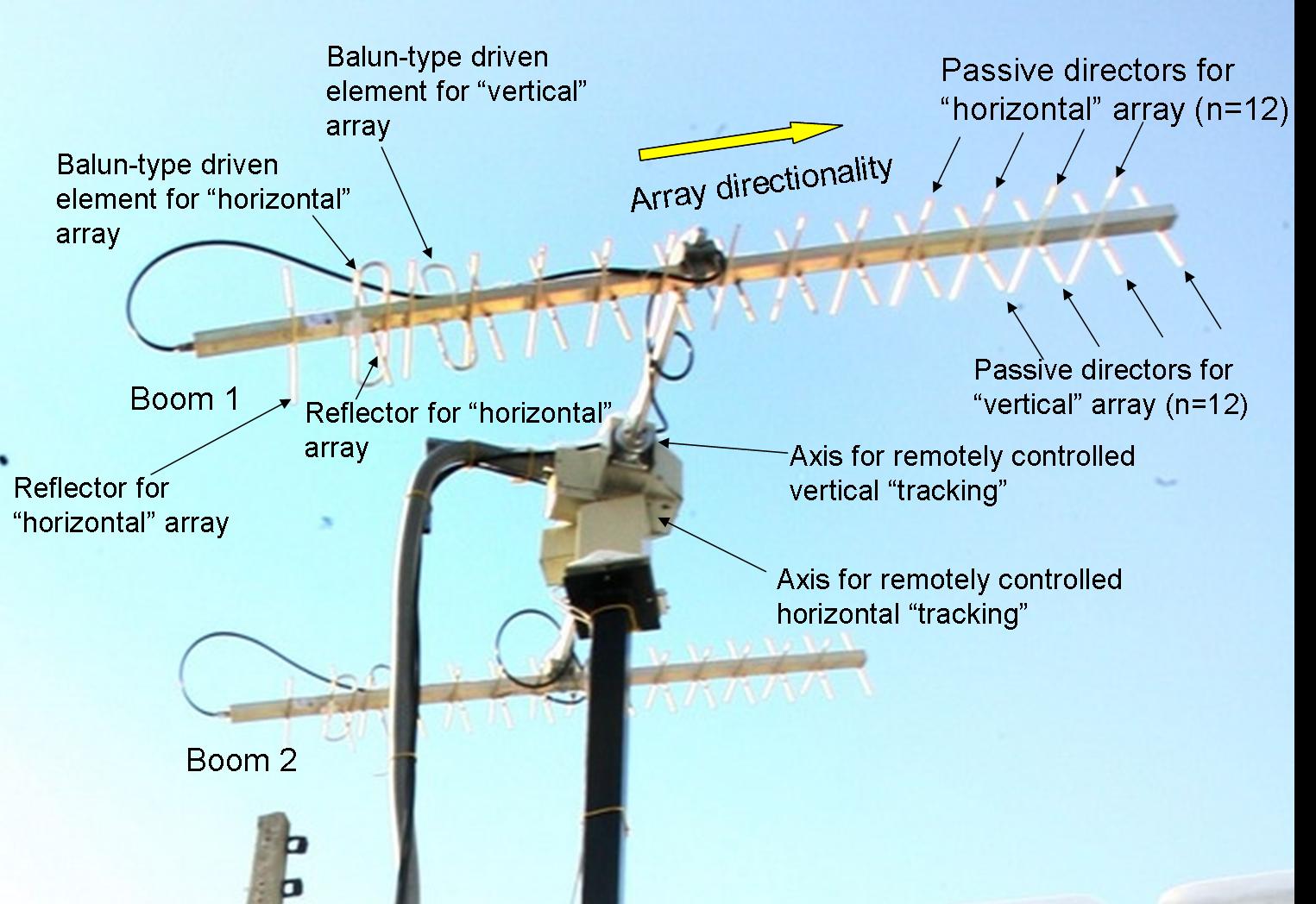
As the image above—taken during a visit to the Iranian Space Center by President Ahmadinejad—shows, there are trucks with potentially suitable antennas. The dual antennas are of a Yagi-Uda design (often simply called a Yagi antenna) with 12 passive “directors,” a looped Balun-type element for radiating the signal and, at the very rear of the array, a somewhat larger “reflector.” The reflector is to ensure that there is a preferred direction to the antenna as opposed to being sensitive to signals from both directions along the boom. The Balun radiator matches the impedance from the simple coaxial cable to the array and the directors increase the “gain” or directionality of the antenna. Interestingly, there are both vertical and horizontal arrays on each boom with the horizontal array set back a quarter wavelength (see below), perfectly suited for detecting or radiating circularly polarized radio waves. That is needed because the Omid satellite tumbles as it orbits and its polarization—while not circular—is directed in an arbitrary, time varying manner. The bulky cable run up to the antenna hub is for controlling the direction of the antenna arrays and could, though there is no way to know from the photo, be capable of autonomous direction if it is set to maximize the strength of the signal.
Yagi antennas are nice from a photo-interpretation point of view because their dimensions are so easily related to their wavelength. For instance, an optimal 13 element (counting the radiator but not the reflector) Yagi for 401 MHz has a boom length of 2.7 meters. That’s from reflector to last director. It also has a reasonable antenna gain, which means that half the uplink beam is radiated into a cone with a half angle of about 16 degrees. The question then becomes: is the observed array consistent with these expectations?
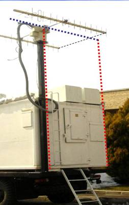
The image to the left is taken from a more suitable perspective for photo-interpretation. The antenna arrays are nearly horizontal and close to being aligned with the rear of the truck. I have drawn two vertical lines continuing up the truck’s rear edges and a third, horizontal, line paralleling the antenna booms. Of course, there are a great number of approximations taken in this drawing. But then again, there are some approximations still to come. The most important of those is to assume that the truck’s rear cabin is approximately two meters in width. With that assumption, we can estimate the boom length to be approximately 2.9 meters long (from radiator to last director). This is consistent with the Omid satellite’s uplink frequency given all the approximations we have made. Either the far antenna in the image is shorter than this (if it is used for the downlink) or they are running the antennas nonoptimally for reception or there is a different receiver somewhere not on the truck.
What I find most interesting is the conclusion that if there are antennas on the Safir that have significantly different lengths than the Omid’s, then these trucks are not being used to communicate with them.

Instead of making an assumption about the read cabin width, isn’t the axle length (and hence wheel distance) likely to be some fairly standard value? It looks like you could measure the distance between the wheels fairly accurately.
Thanks, Geoff, for this unique post.
Also, completely off topic, check out this illustration from XKCD of gravity wells relative to Earth’s surface gravity. It’s a nice introduction to Newton’s constant, and demonstrates why it takes a huge rocket to get to the moon but only a small one to get back. Enjoy!