Yesterday, I discussed the possibility that Iran was learning techniques that might help them utilize higher energy fuels such as UDMH and nitric acid. However, the evidence for such use is rather minimal. The case we examined yesterday was not very convincing and, while there is still room for doubt (see Jochen Schischka’s comments), I think that that the balance of the evidence still leans toward Iran utilizing kerosene/nitric acid combinations. What is know is that Iran is trying to improve its engines and get a higher specific impulse—a measure of how energetic the combination of propellant and engine is—regardless of what fuel it is using. (The technical definition of specific impulse is the thrust delivered by the engine divided by the weight of propellant burned per second.) While Iran’s efforts to do this are most obvious on the Safir’s second stage, it is possible that Iran is also taking the lead away from North Korea in improving the specific impulse of the Shahab/Nodong/Safir 1st stage as well!
People often forget that the design of the engine has a direct effect on the specific impulse and usually compare the theoretical specific impulses of various fuel and oxidizer combinations. If you simply compare these theoretical values for UDMH/nitric acid and RP-1/nitric acid (RP-1 is a kerosene-like fuel similar to the kerosene-based fuel the SCUD uses) you get a ratio of 276/268, in vacuum, and thus an increase of only 3% by going to the more energetic fuel. But the design of the SCUD engine, and in particular, its thrust vector control mechanism robs the propellants of a considerable amount thrust! Consider the images below, which show the jet vanes for the Iraqi Al Samoud II, the SCUD-B, North Korea’s Tae’podong 1, and Iran’s Kavoshgar 1 (which I assume are identical to those on the Shahab and the first stage of the Safir).
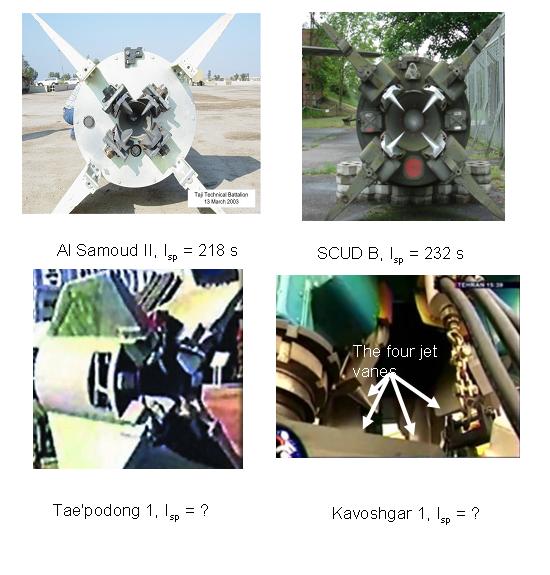
Note the differences in specific impulses, Isp, between the Al Samoud II and the SCUD-B. It is true that these two missiles use different fuels (the Al Samoud uses TEGA 2, aka Tonka, while the SCUD-B uses TM-184; both are hydrocarbons) and will certainly have slightly different base specific impulses. However, it is widely understood that the jet vanes on the Al Samoud II, for instance, rob the engine of as much as 5% of its thrust. This would account for just over 10 s of Isp! It is not too hard to imagine that the SCUD’s larger Isp might, in part, be due to its jet vanes covering somewhat less of the its nozzle exit area. (This, by the way, is what the subtitle of this post is all about.) I’d be interested if any of you out there (John?) wouldn’t mind calculating this effect from first principles.
What I find most interesting about this comparison is that the Iranian jet vanes appear somewhat smaller to me and are, perhaps, angled outwards so that they interact with more of the peripheral part of the exhaust than North Korea’s Tae’podong 1. Is this an indication that Iran has diverged from the Nodong missile it is reported to have imported from North Korea to optimize its thrust? If so, it is an another indication that Iran is leading the way among the so-called proliferating nations: Iran, Syria, North Korea, … in developing better missiles.
This improvement is, of course, a minor one since it still uses jet vanes to control the direction of the first stage’s thrust. But as I mentioned in yesterday’s post, it is more effective to improve the specific impulse of a missile’s second stage. This is exactly what Iran has done by developing a cluster of two gimbaled engines for the second stage of the Safir missile.
Until I started writing these series of posts, I wondered why Iran was putting so much effort into gimbaled engines as opposed to developing a new, higher energy-density propellant combination. Now, I think, we can see the answer. By eliminating the jet vanes, Iran has produced almost the same improvement in delivered thrust as it would get if it had switched to a UDMH/IRFNA combination. Of course, it would be best if Iran did both but doing both at once would significantly increase the development risk and it makes sense for Iran to take these challenges one at a time.
Increasing the effective specific impulse of its engines by removing the jet vanes implies that Iran can cut down not only on the volume (and hence weight) of propellant but also the amount of tankage or dead-weight of the tanks. The next post in this series, on clustering engines, will examine the change in “dead-weight” associated with clustering engines. It will also probably be one of the most techno-wonkish of all this series of posts and I apologize for that in advance.

After acquiring some better pictures of the R-27/Zyb/SSN-6/Serb-two-chamber-vernier-engine and the related turbopump, i am now highly confident that this was in fact the engine displayed to Mr. Ahmedinejad. So the Iranians did perhaps both: doing away with the jet vanes AND switching to a propellant combination with higher Isp (which is by coincidence also hypergolic – a quite elegant solution for upper stage ignition).
And they didn’t even have to design this themselves from the ground up with all the inherent uncertainties – they simply bought proven russian technology.
But of course i can’t be sure that this specific engine was actually installed on the flight-tested Safir-missile.
Here is a better image of Safir:
This is going to be a fantastic series of posts! Very interesting…Bravo! This stuff is so interesting…
I am amazed that they don’t have fluid holes in the jet vane leading edges to transpire fuel/coolant to keep the vanes from boiling away completely!!
Rocket science is not really my area at all, but I can’t resist taking a try at it, it seems to me that in the straight position, the jet vanes are just going to cause blunt nose supersonic drag. Everything else will be small. Let’s consider the possible drag sources :
– nose drag
– supersonic area rule type drag
– boundary layer drag
– erosional/transpirational mass drag
– cooling drag
Did I miss any? Let’s save nose drag for last since that’s going to be the only significant one.
The area rule drag is just due to the taper of the fins over their length. This should drop as the square of the length/thickness ratio, and I can’t see that you will be left with a supersonic Cd of more than 0.1 and probably significantly less especially if there is a taper in the back.
Boundary layer drag will be affected by turbulence, gas composition and a million other things, but I get numbers down in the 0.1% range for this.
Erosional drag is just the required acceleration of eroded graphite from the jet vane. Since it’s mass is kilos and the total fuel is thousands of kilos, it seems like this should be down in the 0.1% range also.
Cooling drag, as I’m calling it, is the reduction in thrust from heat transfer either into the cooling vanes, or into non-pressure producing degrees of freedom in the eroded jet vane material. But, the vanes can’t conduct heat away; I suppose they could radiate some. But, even so notice that the vanes are out past the expansion nozzle, so it is hard to see how the cooling will have much effect anyway. I’d guess this to be negligible.
Finally, we are left with nose drag, and that seems like it will have a supersonic drag coefficient of the order of unity for a blunt leading edge line in the flow. Given the Isp, the flow velocity at the nozzle bottom must be up around 2,300 m/s giving a drag force of ~ 0.5 * fuel Mass flow * v * (fractional area obscured by vanes) = 0.5 * 3770kg/62 sec * 2300m/s * Afrac = 7,000 kgf. Since the total thrust is only about 13,000 kgf, that means that the total Isp loss from the vanes will be (very roughly) 0.5 times the fractional area obscured by the vanes for Cd~1. Again, we don’t know the Cd of an eroded leading edge on the vane with much certainty. Could be a little more, could be a little less.
Now, using an incredibly gross and inaccurate pixel thresholding, I got about 6% of the projected area on the above image as jet vane, leading to maybe 3% reduction in Isp.
So, I’m with Geoff, he’s right that it’s all in the projected area – perhaps a little less than 1% Isp reduction per 1% area obstruction. It would be useful if anyone knows what the supersonic Cd of a leading blunt edge would be in the midst of that firestorm!
Meanwhile, it is clear that when the vanes are turning to steer the missile, it could drop the thrust quite a lot…
Mehdi-
Its certainly a better image but unfortunately they have removed the jet vanes. Presumably they are too delicate to risk somebody bumping into them.
Thanks John! A very complete and readable discussion. I must admit I never would have thought about erosion or cooling drag, though as you point out, they are very small.
Nice work, Mr. Field!
I once got an Cd-0 of approximately 0.6358 for the jet vanes of the german A4/V-2 by retrograde calculation (i hope this helps?). The average loss of thrust on that missile was also close to 3% while initially covering a little less than 8% (4×84cm²/4289cm²) of the nozzle-end-area (there were “noses” on these jet vanes, specifically designed to burn away faster and thus reducing the vane-area during flight – so the actual in-flight-value should have been closer to 6%).
By the way, i was told that the Scud has somewhat similar characteristics, although i don’t have exact dimensions for the jet vanes or specific data on thrust losses of that missile.
Geoffrey,
You can never be too techno-wonkish for an engineer.