Last week, Dafna Linzer had a long, detailed story (and online chat) on intelligence found by German intelligence on a laptop computer stolen by an Iranian citizen in 2004. I am writing a four-part series looking at the key pieces of information: a schematic of a shaft that might be for a nuclear test, plans for an underground facility to produce uranium tetrafluoride (UF4), modifications proposed for the Shahab 3 ballistic missile and the acqisition of relatively advanced P2 centrifuges from Pakistan.
Dafna Linzer’s article on Iranian nuclear activities contained the claim that Iranian engineers in 2002 “completed a set of technical drawings for a small uranium-conversion facility” that would produce uranium tetrafluoride (UF4), although not uranium hexalfuoride (UF6).
Why?
I should note, as Linzer does, that “Nowhere are there construction orders, payment invoices, or more than a handful of names and locations possibly connected to the projects.”
That is in comparison to the very real above-ground Uranium Conversion Facility that Iran is building near Esfahan, based on Chinese designs transferred in the mid-1990s.
Only six countries operate commercial scale uranium conversion facilities.
| Country | Operator | Facility/(ies) | t U/a |
|---|---|---|---|
| Canada | Cameco | Port Hope | 12 500 |
| China | China National Nuclear Corporation | Lanzhou | 1 500 |
| France | Comurhex | Malvesi/Pierrelatte | 14 000 |
| Russia | Minatom | Tomsk/Angarsk | 30 000 |
| UK | BNFL | Springfields Line 4 | 6 000 |
| USA | Converdyn | Metropolis | 14 000 |
Source: IAEA Country Nuclear Fuel Cycle Prolifes 2002, 6.
Esfahan is relatively small facility (285 t U/a). Four other countries can convert smaller amounts with pilot plants, including Argentina (Pilcaniyeu, 62), Brazil (Ipero, 40), India (Trombay, 100), Pakistan (Dera Ghazi Khan, 200). South Africa had a medium sized facility at Valindaba (1400) that has been shut down.
Of these facilities, only the French have a commerical facility that just produces UF4 (Malvesi). The North Koreans have some capacity to produce UF4 at Yongbyon.
Overall, the decision to produce just UF4 baffles me. Why hide a large scale production facility under a mountain if you just plan to truck the UF4 to a different facility some place? Doesn’t exposing shipments to interdiction undermine the security created by burying the facility?
Linzer quotes an analyst offering some hypotheses:
A second facility for uranium gas could have been envisioned as a replacement in the event the United States or Israel bombed the existing one in the city of Isfahan. “It was either their fallback in case we take out Isfahan,” one U.S. analyst said. “Or maybe they considered an alternative indigenous plan but they realized it wasn’t as good as what they already have, and so they shelved it.
Understanding the purpose of the plant is difficult—there are at least two additional pieces of evidence that I think I need.
What is the capacity of the plant?
It would be interesting to understand the size of the clandestine facility. Linzer described it as “small”—although that could mean anything smaller than a commercial-scale facility.
Is the “small” plant a copy of Esfahan (with an output of 285 t UF6/a)? Or is it even smaller, such as Brazil’s facility at Ipero (40 t U/a)?
Size, no matter what you’ve been told, does matter: 100 metric tons of uranium, just for comparison, can be enriched into about 165 kilograms of HEU—enough for 6-8 implosion-type fission devices. A duplicate of Esfahan would makes sense as, well, a replacement for Esfahan. A smaller facility would seem suspicious.
What sort of technology is used to purify the U3O8?
A UF4 plant must remove impurities, such as molybdenum, from the U308 before converting it into UF4.
The Iranian UCF originally called for Chinese-designed “mixer-settlers.” After China cut off assistance, Iran experienced technical trouble with the mixer-settlers and switched to indigenously developed “pulse columns” (one and
two).
It would be interesting to see if the underground UF4 plant was based on Chinese mixer-settlers, the TNRC pulse-columns.
Or maybe indigenous Iranian mixer-settlers, which Iran continues to develop.
Mixer-Settlers v. Pulse Columns
I’ll admit, I find the engineering challenges associated with solvent extraction a little tedious (although I did learn that “crud” is a technical term).
I was looking for a nice, readable description of how to use solvents to extract impurities from uranium. Robert Treybal has a nice entry in Access Science on the various methods:
Extractors bring about direct contact of the feed (solution to be separated) and extracting solvent in order to permit diffusional transfer of the constituents from the feed to the solvent. The rate of transfer depends upon the contact area of the two liquids and the degree of turbulence developed within them. The extractor disperses one of the liquids in the other to produce large surface area, and relative motion to produce turbulence. The extractor must also provide for the subsequent mechanical separation of the dispersion, based upon the different densities of the liquids, to permit withdrawal of the two effluent products, the extract (solvent containing the extracted constituents) and the raffinate (unextracted residue).
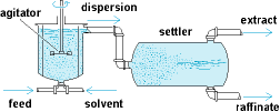
Mixer-settlers (Fig. 1) provide for these requirements in separate vessels. The feed and solvent flow continuously through the mixer, in which the rotating agitator disperses one of the liquids into small droplets immersed in the other. The size of this vessel must provide sufficient residence time for the liquids that the desired diffusional transfer occurs. The degree of agitation must be intense without, however, producing so fine a dispersion that subsequent settling is difficult. The dispersion flows to the settler, most simply a drum, in which low velocity and lack of agitation promote gravity settling and coalescence of the drops to provide clear effluents.
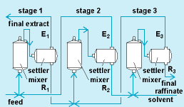
Fig. 1 Single-stage mixer-settler extractor.Since in such single-stage apparatus the extractable substance approaches a concentration equilibrium in the effluents, nearly complete extraction requires a multiplicity of stages. An arrangement for countercurrent interstage flow of the liquids reduces the amount of solvent needed (Fig. 2). The compact modification of Fig. 3 has found particular favor in extraction of radioactive metals from aqueous solutions in processes associated with atomic energy operations.
Fig. 2 Diagram of a three-stage countercurrent mixer-settler extractor. (After R. E. Treybal, Mass Transfer Operations, 2d ed., McGraw-Hill, 1968)
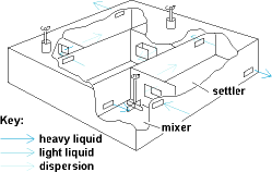
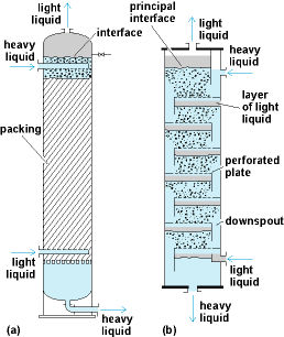
Fig. 3 Three-stage, box-type, mixer-settler extractor.To reduce the floor space and pump requirements for multistage extractors, a variety of vertical towers are also used. These involve countercurrent vertical flow, under gravity, of one of the liquids in dispersed form through a continuum of the other by virtue of the different liquid densities. A packed tower (Fig. 4a) is a cylindrical shell, the bulk of which is filled with manufactured packing, such as rings or saddles, randomly arranged. The more dense liquid, introduced at the top, flows downward as a continuum. The less dense liquid enters at the bottom through small nozzles. The resulting small droplets rise through the heavy liquid, during which time extraction occurs, and then coalesce into a bulk and leave at the top. The packing serves to maintain the dispersion and provide moderate turbulence. The dispersed liquid may be either feed or solvent, light or heavy. If it is heavy, the droplets settle downward. Although the liquids are not repeatedly dispersed and settled as in the multistage mixer-settler, nevertheless multistage effects are obtained. Spray towers contain no packing and are not as effective. See also: Gas absorption operations
Fig. 4 Vertical tower extractors. (a) Packed-tower extractor. (b) Perforated-tray extractor. (After R. E. Treybal, Mass Transfer Operations, 2d ed., McGraw-Hill, 1968)In perforated-tray towers (Fig. 4b) the light liquid collects in a layer under each tray and is dispersed into droplets by the small perforations. The drops rise through the heavy liquid, which flows across each tray and through the downspouts. The frequent redispersion achieved makes these towers very effective. Alternatively, by turning the tower upside down, the heavy liquid may be dispersed.
Mechanical agitation, provided by rotating impellers as in the towers of Fig.5 a, b, and c, is used to obtain finer dispersions and increased turbulence. The pulsed tower (Fig.5 d) provides the mechanical agitation by rapid (20-100 cycles/min), small-amplitude (0.25-2 in. or 0.64-5.0 cm), reciprocating motion superimposed upon the natural flow of liquids as they alternately pass through small perforations in the plates. This is particularly useful for handling radioactive liquids, since moving parts may be located in a place of safety.
In all these designs, the tower diameter is governed by the quantity of liquids to be handled, the height by the number of stages of extraction required. Towers up to 15 ft (4.8 m) in diameter and 125 ft (38 m) tall have been built. Auxiliary equipment may include pumps for movement of the liquids, motor drives for agitators, valves and flowmeters for control of flow rates, and liquid-level control instruments.
Robert E. Treybal, “Solvent extraction”, in AccessScience@McGraw-Hill, http://www.accessscience.com, DOI 10.1036/1097-8542.636100, last modified: February 26, 2001.
The whole article is worth a read, really (subscription only).

Dr. Jeffery wrote:
“Overall, the decision to produce just UF4 baffles me. Why hide a large scale production facility under a mountain…”
It seems to me that the most straightforward reason would be that Iran is building a parallel enrichment system using calutrons (just as the US did for Little Boy and as Iraq did).
Calutrons use UF4 as feedstock (plus it isn’t nearly as fussy as centrifuges as to quality.) Iran has had much experience and training with a couple of imported small calutrons and certainly have the skills to build hidden racetracks at distributed sites.
Also “165 kilograms of HEU—enough for 6-8 implosion-type fission devices.” seems a bit conservative.
The crit mass of 93.5% HEU is 18.4 kg with a thick NatU tamper or 14.1 kg with a thick Beryllium tamper.
This works out to
~9-12 Trinity-scale bombs (~4 critical masses at max compression)
If you ease off a bit (and still yield many kilotons), an antique Trinity-style implosion system (2x compression) would give 2 critical masses with only 9kg (w/NatU) or 7kg (w/Be).
Therefore the same 165 kg of HEU gets you 18 to 24 multi-kiloton bombs.
The same 165 kgs would allow 4 double-gun-assembly uranium warheads (wasteful of HEU but quite compact and lightweight and perfect for missiles).
Ahh, the dangers of working in a rush. Just realized we are talking about uranium hexafluoride (uf4) and not uranium tetrachloride (ucl4). Last time I post while working on my taxes!
;-P
yale
I gotta give up…
uranium TETRAfluoride not hexa.
Proofreading is not my specialty…
Let me try to simplify the concept of solvent extraction (the general term for what happens in mixer-settlers and other apparatus described in the quote).
Take two liquids, an oily one and a watery one, that don’t mix. Dissolve the stuff you want to purify in one of them. The stuff you want and the impurities must be soluble in different phases. This can be helped by adding agents to one phase or the other that will chemically grab the various components. Now shake it all together.
The process has to be repeated many times, depending on how much difference there is in the solubilities of the various components. It’s like rinsing the soap out of a garment. The rinse water doesn’t dissolve it all the first time, so you have to repeat.
Okay, so solvent extraction is the high technology that Iran can never master without Chinese help?
Or, maybe they can, but it’s so difficult it constitutes the critical bottleneck, and thus the Russian enrichment plan is “a really bad idea” because it would allow the Iranians to work out the bugs in this really tricky process, which otherwise would stand in their way?
Are officials anywhere discussing/looking into a clandestine Iranian calutron method of enriching uranium in addition to whatever they are doing / attempting to do with centrifuges? Is this a reasonable line of inquiry?
You refer to “the underground UF4 plant” when no such plant is known to exist, and when the Laptop from Heaven itself is quite obviously a plant. Please, lets not allow all the technical speculation over-take those two rather significant facts!
Yale Simkin wrote…
“Proofreading is not my specialty…”
Yale once told me that no country would ever step away from the nuclear non-proliferation treaty. Not in a thousand years. Shortly afterwards N.Korea did exactly that. Other ill considered “predictions” include Breeder Reactors “never ever” making a comeback. That was shortly before India did in fact bring them back. So be wary of his “predictions” if he espouses any. In fact I’d check his facts constantly. He has a habit of twisting reality to his suit his own needs if you understand my meaning. He has been banned from Space.com as seekerbot. Banned from sciforums as therealyales and a host of other respected forums for repeatedly hacking them. Now getting back to Iran, I find it funny that Mr Yale is stipulating a secret UF4 plant when he once refused to accept the possibility of a blackmarket trade in Uranium. Seemed like commonsense to me. Perhaps I should point out that he is also violently anti-nuclear and frequently trolls pro-nuclear forums. That seems to be his “specialty”.