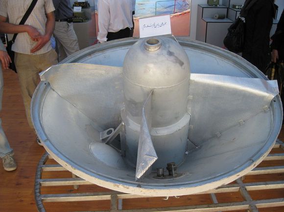
Iran is justifiably proud of its satellite launch last February. After all, both North and South Korea failed in their satellite attempts in that same year. It appears from images that are starting to show up on the web—pointed out to me by the ever observant Wonk-Reader Tal Inbar—that they have taken the show given to President Ahmadinejad at the Iranian Space Center on the road. These images show new and revealing details of both the Safir/Omid system and some indication of the quality of workmanship that goes into it. The image above is another image of the back of the Safir’s second stage engine platform showing more about how the turbopump is enclosed. Compare it to the image shown here, which shows more of the turbopump. The very frail looking “flaps” are light-weight baffles to prevent the fuel from sloshing about particularly during staging. Other images show what appear to be drain holes to the fuel tanks, a new telemetry dish antenna, and several nice views of the first stage engine (and are those indigenously produced components laid out on little pedestals?) Any help translating the Farsi on any and all these images would be gratefully appreciated!

Note the disappearance of the “ribs” on the back of the engine mount cone from previous images to this one. Wild speculation: could those have been an early design of a baffle system that didn’t live up to expectations? Up until now, I’ve thought of them as strengthening members but with their disappearance perhaps we should consider other possibilities.
Hi Geoff
I use this free site for Farsi/Persian to English translation. It works pretty good and should give you a rough idea of what is being described: http://translation.babylon.com/English/to-Persian
1-http://commons.wikimedia.org/wiki/File:Omid_0663.jpg
Lower conical of second stage
2-
http://commons.wikimedia.org/wiki/File:Omid_0658.jpg
Motor of the first stage
3-http://commons.wikimedia.org/wiki/File:Omid_0660.jpg
Motor Parts
4-http://commons.wikimedia.org/wiki/File:Omid_0664.jpg
Bulky maquette of Omid satellite
5-http://commons.wikimedia.org/wiki/File:Omid_0668.jpg
Mobile Station for Transmission
6-
http://commons.wikimedia.org/wiki/File:Omid_0666.jpg
Preflight sample
7-http://commons.wikimedia.org/wiki/File:Omid_0667.jpg
Bulky maquette of Sina satellite
Thy also use fiberglass instead of Aluminum on the lower section of the missile’s canopy.
See: http://commons.wikimedia.org/wiki/File:Omid_0661.jpg
The poor craftsmanship is clearly seen, but none the less, it saves a lot of weight – that could be translated to the weight of the satellite or the orbit achieved.
Could this be a non-functional prop wielded together by interns for the express purpose of an exhibit?
One of the the baffle setups could be an earlier design, but all you can say about the objects is that they were fabricated sometime before the pictures were taken. One doesn’t necessarily put the latest and greatest gear in a trade show or whatever that was.
Thanks Amir, thats very helpful! For image 660, do the little signs say “motor parts” or are they more specific?
Image 660: the three signs on the right side say, “motor parts,” while the (single) sign on the left side says, “signaler.”
File:Omid_0661.jpg
It says:
“Satellite Protector
A Physical Component”
I cannot properly read the second sign behind (with the giant ring) but it says:
“[sth][sth] in the first stage”
lol sorry
Geoff
It’s just motor parts
Thanks Bahram! It is certainly a motor part but “signaler” is very suggestive. Could it, for instance, be a combustion chamber pressure guage? The square bit in the center–where the bolts hold the two “halves” together–could hold a bladder to amplify any pressure difference between actual and desired.
Nice pictures (thank you, Tal Inbar, Geoff and especially everybody who’s helping with Farsi-translations)!
Somehow, this reminds me of photos from the ’89 Baghdad Arms Expo – the Iraqis exhibited a rather similar conglomeration of parts from their missile rev-eng-efforts back then (everybody, please keep in mind that we likewise don’t know anything about the quality of the exhibited iranian parts, either – most likely, those are at best rejected parts unfit for a flight-unit, as is quite common for such exhibitions – and we also don’t know for sure if they were even manufactured in Iran)…
Nonetheless, this shows us interesting details of the internals of the Safir (and indirectly also the Shahab-3 and the Ghadr-1, since those missiles apparently use the same main engine).
In the background to the right of photo Omid_0662.jpg we can see the ‘Heckring’ (aka the end plate of the lower stage’s engine section) with openings for the engine, the turbine exhaust, the Sh-37 and -38 boxes and the triangular three-fold-coupling.
Considering photo Omid_0663.jpg, i agree with Geoff, the four perforated sheets (i guess they are not rumpled like that on the real flight-units) most likely are slosh baffles (and the rib-like structures on earlier exhibits may offer a nice explanation for the failure of Safir-1 – analogous to the second Falcon-1 launch). Another interesting detail in that picture is the first-time completely shown turbopump-canister (noteworthy: only one opening for a propellant line – oxidiser? – on top).
Omid_0661.jpg shows us part of the nose fairing, obviously made of GFRP (this may be a shock to others, but from my own experience, i’d say that that ‘makeshift’-like look is quite common for that type of material in unpainted condition, even if professionally laminated to aerospace-specifications…BTW, GFRP per se won’t result in significant weight savings compared to aluminum, since both materials have rather similar properties in an isotropic case – but fibre-reinforced plastics offer the advantage of ‘tailoring’ the laminate according to the loading conditions, aka ‘cutting away’ unneccessary tensile strength in less-stressed directions, and it’s also possible to intermix e.g. (yellowish) Aramid-fibres…).
Photo Omid_0659.jpg offers a good look at the fins of the Safir IRILV: similar dimensions and layout as Scud-fins, but not identical (apart from the longer opening for the larger Nodong-jet-vane-cover, there’s also an additional rib in the lower part of the fin compared to the Scud’s).
Last but not least, photos Omid_0650.jpg, Omid_0651.jpg, Omid_0652.jpg (excellent shot of the rear end!) and Omid_0654.jpg once again show the Safir mock-up (as in 2008 and 2009). Before everybody starts with detailed measurements and theorizing about the layout of that launcher based on that item, let me warn you all that this thing significantly differs in several aspects from the real flight-units (e.g. large Nodong-fins – compare the rivet-lines in photos Omid_0652.jpg and Omid_0659.jpg, visible intertank section, partially bolted tank-sections, too short cable duct with inconsistent length, no double-weld-seams at the endcaps or no tank-endcaps at all etc., etc., etc.) – so, i’d advise on taking that particular exhibit with a grain of salt.
Its great to have wonk-readers who can decipher nastaliq writing. The staff here at the Wonk appreciate your input!
Jochen, the baffles are “rumpled” like that because they are supposed to be attached to the cylindrical portion of the fuel tank as well. Since the cylindrical portion is not there, they hang loose.
Great thread!
Geoff,
I mostly agree with you on the issue of the baffles. Yes, they are most likely ‘rumpled’ because they were unhitched from the cylindrical rocket body/tank wall (it’s possible to identify the corresponding fittings on these baffles on close examination). But my guess is that these baffles are made from perforated sheet metal (possibly aluminum, since the fittings of these structures are apparently riveted on the baffle-side and welded on the steel? tank-wall side) and thus would be stiff enough to not sag like that due to gravity alone. According to my interpretation, the ‘rumpling’ might be associated with a rather ungentle disassembly or transport of that particular exhibit.
BTW, it’s also interesting to note that the Iranians obviously haven’t found out yet that bonding is superior to riveting, especially considering FRPs (see picture Omid_0661.jpg of the lower part of the payload fairing). In fact, i consider riveting (especially non-counter-sunk) in this context as rather, eeehhh, ‘unconventional’…
Meanwhile, i’ve taken a closer look at picture Omid_0660.jpg (the one with the ‘engine parts’):
upper shelf (from right to left):
R-27-vernier-chamber without injection head or nozzle extension – associated fuel and oxidiser injectors (the small parts in front) – unidentified (i know i’ve seen something like that before, but at the moment, i just can’t put my finger on it…)
middle shelf (FRTL):
unidentified – unidentified – injection head (R-27-vernier-chamber) – copper inner wall (R-27-vernier) – connecting flange of fuel line (Nodong-engine) – connecting flange of oxidiser line (Nodong-engine) – unidentified (possibly part of pressure or thrust regulation valve of Nodong-engine?)
lower shelf (FRTL):
unidentified – gimbaling fork (for R-27-vernier-chamber) – unidentified (possibly part of a Nodong-engine pressure or thrust regulation valve?) – unidentified – the ‘signaler’: part of the gimbaling hydraulics of the R-27-vernier-chamber – part of gimbaling mechanism of R-27-vernier
Considering the last two items, compare them with this picture from the february-2008-presentation:
!http://www.b14643.de/Spacerockets_1/Diverse/Safir-IRILV/SAFIR_13.jpg!
I can identify two of these ‘signaler’-boxes fitted to the back of that exhibit plus, most likely, the small cylindrical object directly adjacent to the hydraulic actuator.