ACW readers love to analyze photographs and foreign missiles so I thought I would have a little contest: identifying components of the Safir second stage engine. I’ve been staring at a couple of images of the reverse side of the Safir second stage for a couple of days now trying to make sense of it (especially when compared to the test stand version I discussed quite a while ago!)They really do not look like the same thing to me. Here is a comparison between the two “reverse sides”:
click on the image for a larger version
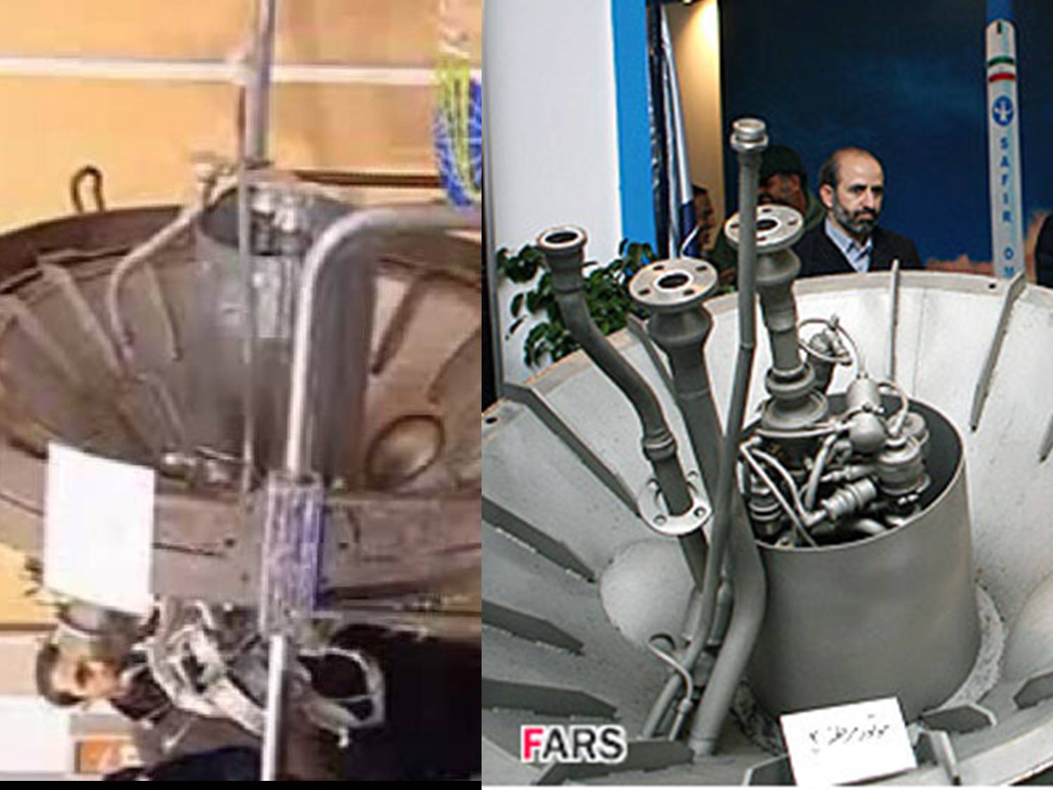
The “test stand” item is on the left, the “display item” is on the right”
For one thing, there seems to me to be too much “stuff” in central compartment for it to be only a turbopump that feeds two engines on the underside of the test stand version. Of course, the test stand item’s “protective cylinder” is longer and therefore can hide more. But, even still, the propellant pipes are arranged differently. I’m sure ACW readers will see other interesting things about this comparison.
However, even if I cannot make any sense of it, the combined might of the ACW readership should be able to! So I thought I’d make it into a contest. In the picture below (which ACW reader Tal Inbar sent me), I have zoomed up on the business end of the reverse side and tagged some of the visible components with numbers. On the side, I have listed some of the possibilities. Of course, there might be other possibilities. And nobody says that all the possibilities listed have to be visible. But it’s a starting place.
click on the image for a larger version
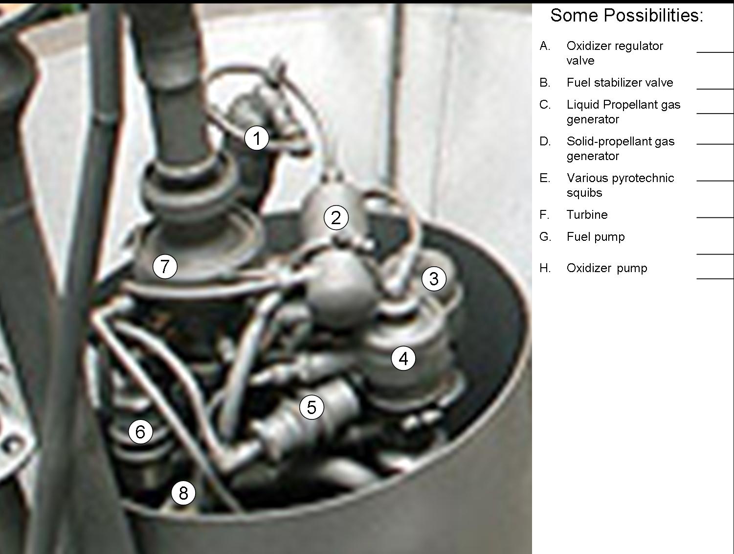
I’ll buy the winner a beer if we are ever in the same city. Of course, I won’t be deciding on the winner. You readers will have to decide who makes the most sense.

To further wet your interest, ACW reader Tal Inbar sends this image (which he believes is the Safir second stage engine):
!http://www.armscontrolwonk.com/images/1287.jpg!
What surprises me a bit are the welding seams of the structure. It’s clearly NOT an Aluminum alloy and they look like the seams of a steel alloy (or maybe Titanium, but I don’t think so). This would make the structure quite heavy.
Tal Inbar’s latest picture is interesting too! It reminds me off the good old SAM 2 sustainer engines. I will consult my archives of SAM 2 pictures to see whether I am wrong or not
Tal Inbar’s image clearly shows the SA-2 Volga motor, version S2.711B. This is not the upper stage motor.
Actually Iran produces SA-2,here are some photos:
The two flanged pipes with identical fittings and flare/taper sections right behind the fitting look like they’re for the same liquid, but they end up in different places in the engine.
Since the skinnier pipe also goes off-center, and the nozzles in the older pics are shown off-center, I’m going to guess that the center pipe goes to a pre-burner/gas generator. The outboard pipes go to a manifold and then split to the nozzles we saw in the older photos, and the inboard pipes run the generator and vent their exhaust down the centerline.
Then again, items 1/2 and 5/6 look like duplicates to me. If the test stand version (2 nozzles) is the engine they’re using, then these could be the port and starboard equivalents of the same parts, and the split to left and right engines occurs down inside the sleeve. No idea what these parts’ functions are, though.
Item 7 looks like a flex coupling or some kind of valve to regulate incoming fuel flow.
Last but not least, I think that the cylindrical sleeve – visibly different in the two diagrams – is intended to hide the turbopump and/or other important parts. This could be to disguise their capability, their origin, or both. If the sleeve were intended to reduce the risk of handling damage, they could remove it to show more parts. Given their willingness to show off the rest of the engine, I’m guessing there’s something about that turbopump that is very distinctive.
As i already wrote yesterday on the thread “Is the Safir 2 or 3 Stages?” (but my comment has not yet appeared there): Tal Inbar’s engine is, as Markus Schiller already pointed out, an Isayev S2.711V (i think it’s a kyrillic “B”) of the Sayad-1/HQ-2/CSA-1/V-750V/D-11/Desna/SA-2b/Guideline mod.1 – you can even see that missile in the background of that particular photo (it’s obviously the same display as in the photos Omid was so kind to provide). What could have lead to this misunderstanding is that the SA-2B also is a two-staged missile: double-base booster + IRFNA/Tonka sustainer (-> “second stage engine”).
Hi there,
I wanted to know the cost of the safir rocket and omid satellite? How much iran will spent to launch this satellite?
Anybody:
Please compare the visible part of the displayed Safir upper stage engine (turbopump) with this exhibit at the museum at the russian Orevo (especially the right side of the photo; i think this is the part peeking out of the shortened canister of the iranian device):
http://www.novosti-kosmonavtiki.ru/content/photogallery/gallery_031/images/IMG_2673.jpg
As far as i understand, the accompaning text describes this as (a turbopump of) a “rudder chamber ZhRD 4D10” of an R-27-SLBM (=SSN-6/Serb), “designed by Isayev”.
Jochen,
I think you have hit on something here! Note the “nozzle” to the exhaust manifold appears very similar to the “nozzle” on the business end of the test stand item. Also, since the picture you found is a training (or the equivalent) item it has the turbo and pumps sliced open and you can see that the turbopump axis parallel to the exhaust manifold axis. I would even venture to guess that the pipe that appears parallel and running below the exhaust manifold is a propellant intake pipe, (though which one might take some staring at!) If so, it could connect up with one of the other pipes that appears to run on the outside of the display item. Good work! It explains a lot!
An immediate question that comes to mind,however, is whether or not the turbopump is really immersed? My immediate impression is that space below the end of the pipes and the bottom of the 2nd stage must be dead area. But this significantly reduces the volume for propellant. What is your opinion? Of course, it is possible that the other pipe on the outside of turbopump chamber, is attached to a pump that moves sucks the propellant out the bottom and moves it back up to the other end of its neighbor pipe. But that seems awfully complicated!
Finally, this really convinces me that the Iranians got this pump from the Russians. There is no way they would design and build a pump with such a radial redesign.
I think we can probably alsow follow the piping around from these two images to really determine what the different components do. I’ll buy you a beer some time!
ps I think #8 is the turbo that has been rotated 90 degrees!
pps ACW readers are the best!
In my opinion, BOTH examples of this upper-stage-engine-assembly displayed so far probably are only test-rigs for ground tests or engineering mock-ups differing most likely in certain aspects from the real flight-units.
This would explain A.) why the canister (pointless if NOT submerged in the lower propellant tank; i also think that there would be BY FAR too little propellant-volume available on the upper-stage to explain either the take-off-weight of ~26t or the apparent performance-envelope of the Safir/Taep’oDong-B?) is not closed around the turbopump and has a different length in both cases and B.) why both propellant-lines (the thicker ones with roughly the same diameter -> about the same dV/dt!), one leading directly inside the top of the turbopump, the other one going all the way around the canister, end side by side in a similar flange (since it would certainly be more comfortable and safe to test the engine-assembly alone while feeding it from separate reservoirs via supply lines with integrated conventional multi-use valves instead of the single-use valves typically utilized on flight-units).
I’m still puzzling over why there are two additional pipes (a smaller, longer one + a somewhat shorter, thicker one) on the outside of the pump-canister, though; The gas-generator would with high probability branch the necessary propellants off of the main-lines after the turbopump (allocated by the thrust/oxidiser regulation valve), so i’d exclude that possibility; Any ideas on this issue?
BTW, i think that (with a little good-will, since the quality of the 2008-image is arguably not the best) the same or very similar tubing can be identified on the february-2008 and -2009 display-items. Also note the similar orientation of the tubing in respect to the thrust-chambers (or rather the bulges for them in the conic structure – are there chambers present at all in the 02-2009-exhibit? I can’t find them on the pictures i’ve seen so far…).
I am disturbed by the variation I notice in the quality of the various visible welds. The quality of the welds and the bending of the fuel tubes seem to be at least problematic for high stress connections, as in fuel tanks.